Table of Contents
The Heltec LoRA V4 is NOICE!!!!
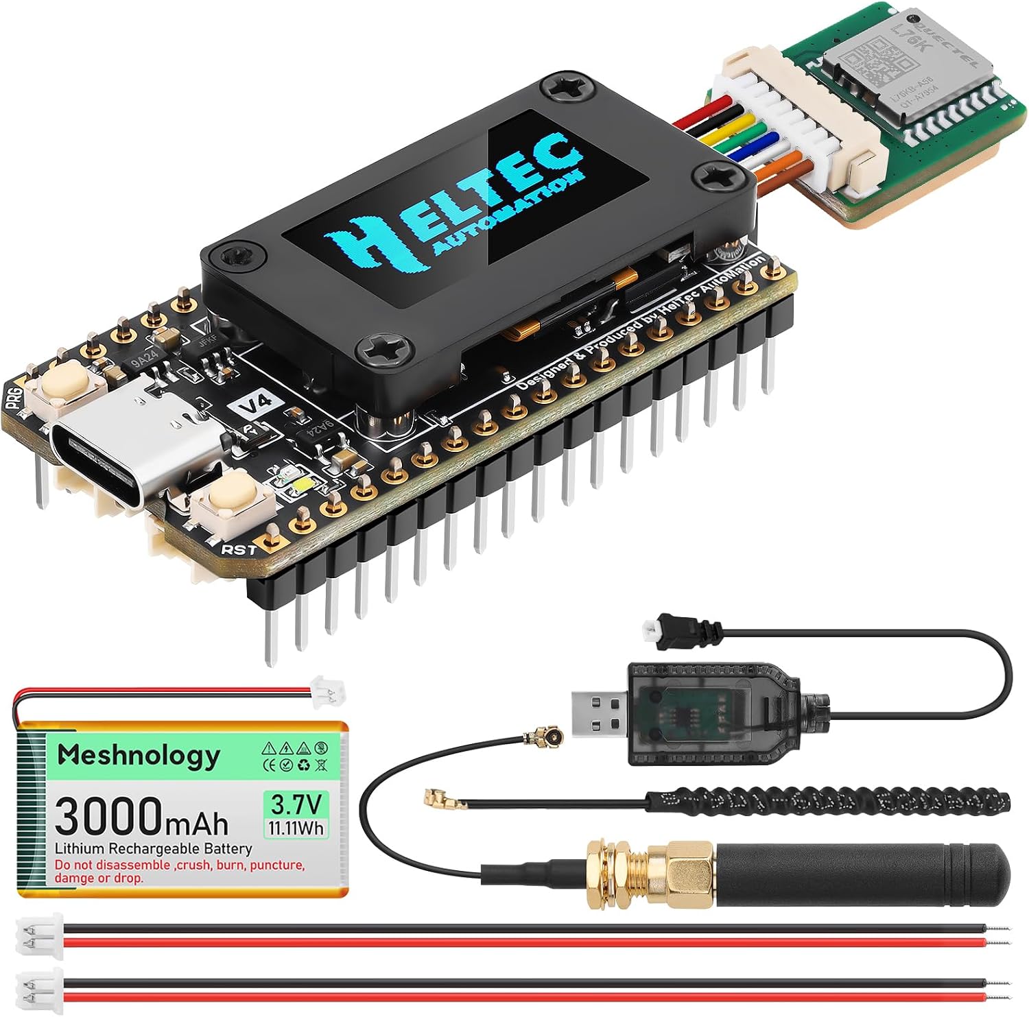
So while working on Project Aziz I upgraded by dev board from the Heltec V3 to the Heltec V4 with solar and GNSS. This simple hardware upgrade saved me countless hours of configuring and soldering. Of course in order to get familiar with the new microcontroller I wrote a simple C++ application to grab my GPS coordinates and display my speed and altitude.
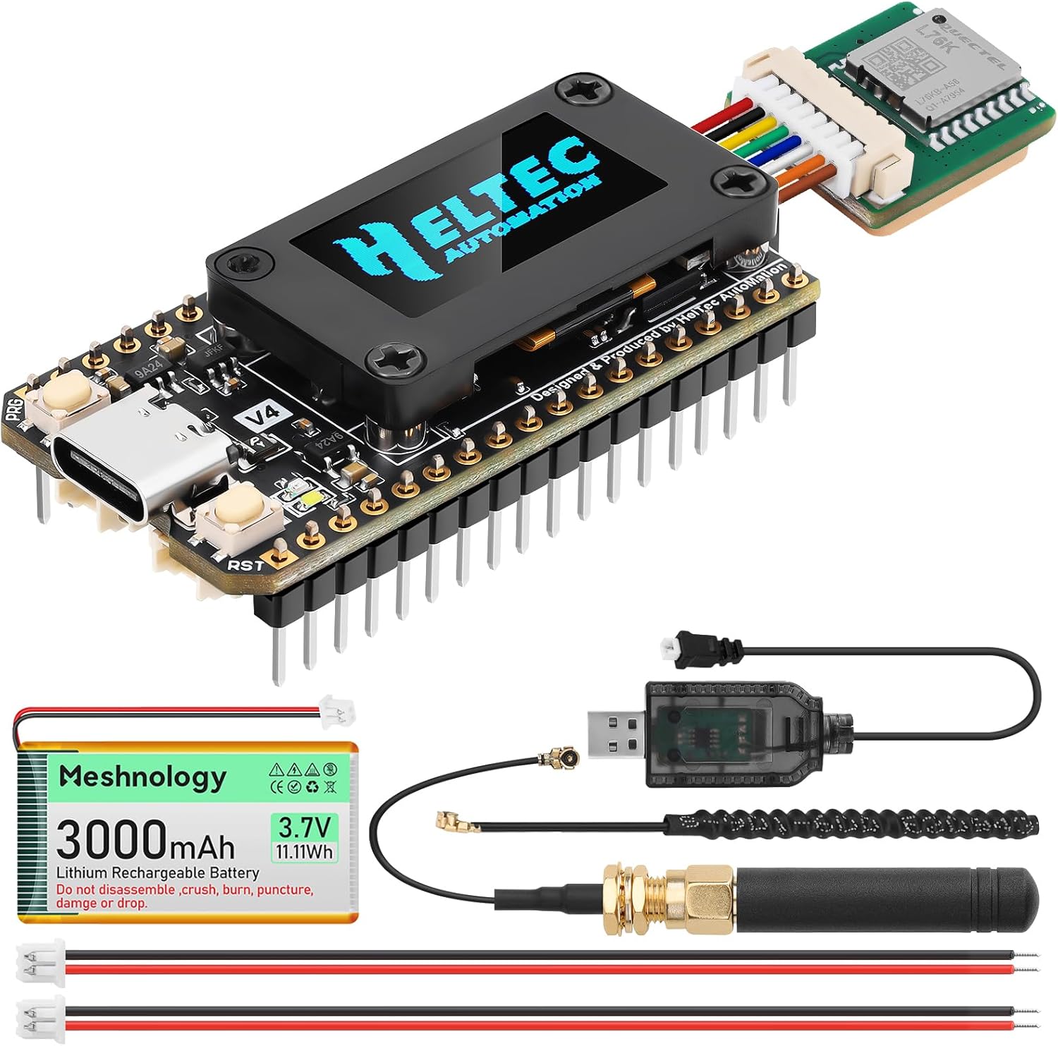
The application is very simple the Heltec V4 comes with a dedicated SH1.25-8Pin GNSS interface for the GNSS module and it spits out raw NMEA strings for parsing the GPS data (you can read more on NMEA here). Pin 38 is the RX pin for receiving data from the module, pin 34 powers it, pin 42 is the GNSS reset and pin 40 is for GNSS standby, lastly the baud rate is set at 9600. Knowing this let’s get started with the Platform.io C++ application.
Platform.ini
; PlatformIO Project Configuration File
;
;   Build options: build flags, source filter
;   Upload options: custom upload port, speed and extra flags
;   Library options: dependencies, extra library storages
;   Advanced options: extra scripting
;
; Please visit documentation for the other options and examples
; https://docs.platformio.org/page/projectconf.html

[env:heltec_wifi_lora_32_V3]
platform = https://github.com/pioarduino/platform-espressif32/releases/download/stable/platform-espressif32.zip
board = heltec_wifi_lora_32_V3
framework = arduino
lib_deps =
	mikalhart/TinyGPSPlus@^1.1.0
	adafruit/Adafruit SSD1306@^2.5.17
	adafruit/Adafruit GFX Library@^1.12.6
; Route Serial to the USB-C port (native USB CDC). Without this flag, Serial
; prints go to UART0 pins 43/44 and the serial monitor shows nothing.
build_flags = -DARDUINO_USB_CDC_ON_BOOT=1
monitor_speed = 115200
In the .ini file I created an environment for the heltec wifi lora 32 v3 because Platform.io vscode extension did not have the v4 board in the list however it is no issue for this application they are functionally the same for what I needed. Next I added the library dependencies:
– TinyGPSPlus for parsing NMEA strings easily
– Adafruit SSD1306 and Adafruit GFX Library to work with the onboard LCD
With that out of the way let’s move on to the simple and elegant main.cpp file.
Main.cpp
#include <Wire.h>
#include <Adafruit_GFX.h>
#include <Adafruit_SSD1306.h>
#include <TinyGPS++.h>

// Onboard OLED Definitions for Heltec WiFi LoRa 32 V4
#define SCREEN_WIDTH 128
#define SCREEN_HEIGHT 64
#define OLED_RESET    21 // OLED reset line is wired to GPIO 21 on this board
#define SCREEN_ADDRESS 0x3C /// Standard I2C address for SSD1306
#define VEXT_PIN      36 // Vext power rail switch (active LOW) — powers the OLED

// Hardware Pins for GPS Module — Heltec V4 dedicated GNSS interface
// (the SH1.25-8P socket; also broken out on header J3). Confirmed against
// Meshtastic's heltec_v4 variant:
//   GPIO 38 carries data toward the CPU (ESP32 receives here)
//   GPIO 39 carries data toward the GPS
//   GPIO 34 is the GNSS power enable, ACTIVE LOW — module is dead without it
#define GPS_RX_PIN    38 // ESP32 receive line (data from GNSS module)
#define GPS_TX_PIN    39 // ESP32 transmit line — unused, we listen only
#define GNSS_EN_PIN   34 // GNSS power enable, drive LOW to power the module
#define GNSS_RST_PIN  42 // GNSS reset — LOW for >100ms resets; hold HIGH to run
#define GNSS_WAKE_PIN 40 // GNSS standby: HIGH = force awake, LOW = allow sleep
#define GPS_BAUDRATE 9600 // Heltec L76K GNSS module factory default

// Object Instances
Adafruit_SSD1306 display(SCREEN_WIDTH, SCREEN_HEIGHT, &Wire, OLED_RESET);
TinyGPSPlus gps;
HardwareSerial gpsSerial(1); // Use HardwareSerial 1

uint32_t gpsBaud = GPS_BAUDRATE;   // Actual baud found by detectGps()
int8_t gpsRxPin = GPS_RX_PIN;      // Actual receive pin found by detectGps()
unsigned long lastDiagDraw = 0;    // Last time the diagnostic screen was drawn

// Listen (receive-only) on a candidate pin/baud and decide whether real NMEA
// text is coming in: mostly printable characters with '$' sentence markers.
// TX stays detached — we never send to the module, and keeping the second
// GNSS line undriven avoids bus contention if the pin roles are swapped.
bool probeGps(int8_t rxPin, uint32_t baud) {
  gpsSerial.end();
  gpsSerial.begin(baud, SERIAL_8N1, rxPin, -1);
  while (gpsSerial.available()) gpsSerial.read(); // drop stale garbage
  unsigned long start = millis();
  uint16_t total = 0, dollars = 0, printable = 0;
  while (millis() - start < 1300) {
    while (gpsSerial.available()) {
      char c = gpsSerial.read();
      total++;
      if (c == '$') dollars++;
      if ((c >= 32 && c <= 126) || c == '\r' || c == '\n') printable++;
    }
  }
  Serial.printf("Probe RX=%d @%lu: %u bytes, %u '$', %u printable\n",
                rxPin, (unsigned long)baud, total, dollars, printable);
  return total >= 20 && dollars >= 2 && printable >= (uint16_t)((total * 9) / 10);
}

// The datasheet's GNSS_TX/GNSS_RX net names are direction-ambiguous, and
// Heltec GNSS modules ship at different bauds (L76K: 9600, UC6580: 115200).
// Try listening on both pins at every common baud until NMEA appears.
bool detectGps() {
  static const uint32_t bauds[] = {9600, 115200, 38400, 57600, 19200, 4800};
  static const int8_t rxPins[] = {GPS_RX_PIN, GPS_TX_PIN};
  for (int8_t pin : rxPins) {
    for (uint32_t baud : bauds) {
      // Show progress on the splash screen's bottom line
      display.fillRect(0, 50, SCREEN_WIDTH, 14, SSD1306_BLACK);
      display.setCursor(10, 50);
      display.print("RX");
      display.print(pin);
      display.print(" @ ");
      display.print(baud);
      display.display();
      if (probeGps(pin, baud)) {
        gpsRxPin = pin;
        gpsBaud = baud;
        return true;
      }
    }
  }
  return false;
}

void updateDashboard() {
  display.clearDisplay();
  display.setTextSize(1);
  display.setTextColor(SSD1306_WHITE);

  // Row 1: Latitude & Longitude
  display.setCursor(0, 0);
  display.print("LAT: ");
  if (gps.location.isValid()) display.println(gps.location.lat(), 5);
  else display.println("SEARCHING");

  display.setCursor(0, 12);
  display.print("LON: ");
  if (gps.location.isValid()) display.println(gps.location.lng(), 5);
  else display.println("SEARCHING");

  // Draw a visual separator line
  display.drawFastHLine(0, 24, 128, SSD1306_WHITE);

  // Row 2: Speed (Formatted to look prominent)
  display.setCursor(0, 28);
  display.print("SPEED: ");
  if (gps.speed.isValid()) {
    display.print(gps.speed.mph(), 1); // Change to .kmph() if preferred
    display.println(" mph");
  } else {
    display.println("0.0");
  }

  // Row 3: Heading (Course)
  display.setCursor(0, 40);
  display.print("HEAD:  ");
  if (gps.course.isValid()) {
    display.print(gps.course.deg(), 1);
    display.print(" deg (");
    display.print(TinyGPSPlus::cardinal(gps.course.value()));
    display.println(")");
  } else {
    display.println("---");
  }

  // Row 4: Altitude & Satellites
  display.setCursor(0, 52);
  display.print("ALT:  ");
  if (gps.altitude.isValid()) {
    display.print(gps.altitude.feet(), 0); // Change to .meters() if preferred
    display.print(" ft");
  } else {
    display.print("---");
  }

  // Quick system health indicator in bottom right corner
  display.setCursor(95, 52);
  display.print("S:");
  display.print(gps.satellites.value());

  // Push buffer to the physical OLED panel
  display.display();
}

void setup() {
  Serial.begin(115200);

  // Power on the Vext rail first — it feeds both the OLED and the GNSS socket.
  // Switched by GPIO 36, active LOW.
  pinMode(VEXT_PIN, OUTPUT);
  digitalWrite(VEXT_PIN, LOW);
  delay(100); // Let the rail stabilize before talking to peripherals

  // Power the GNSS module — it has its own enable line in addition to Vext
  pinMode(GNSS_EN_PIN, OUTPUT);
  digitalWrite(GNSS_EN_PIN, LOW);

  // Release the GNSS module from reset and keep it awake
  pinMode(GNSS_RST_PIN, OUTPUT);
  digitalWrite(GNSS_RST_PIN, HIGH);
  pinMode(GNSS_WAKE_PIN, OUTPUT);
  digitalWrite(GNSS_WAKE_PIN, HIGH);
  delay(1000); // L76K warmup before it starts streaming NMEA

  // Initialize Onboard I2C for the OLED Screen
  // Heltec V4 onboard OLED I2C pins: SDA = 17, SCL = 18
  Wire.begin(17, 18);

  if(!display.begin(SSD1306_SWITCHCAPVCC, SCREEN_ADDRESS)) {
    Serial.println(F("SSD1306 allocation failed"));
    for(;;); // Don't proceed, loop forever
  }

  // Initial Splash Screen
  display.clearDisplay();
  display.setTextSize(1);
  display.setTextColor(SSD1306_WHITE);
  display.setCursor(10, 20);
  display.println("GPS DASHBOARD");
  display.setCursor(10, 35);
  display.println("Detecting GPS...");
  display.display();

  // Find the module's receive pin and baud rate, then listen there
  if (!detectGps()) {
    // Nothing intelligible heard anywhere; fall back to defaults so the
    // loop() diagnostics can show what's (not) arriving
    gpsSerial.end();
    gpsSerial.begin(GPS_BAUDRATE, SERIAL_8N1, GPS_RX_PIN, -1);
  }
  Serial.printf("Using GPS RX=%d @ %lu\n", gpsRxPin, (unsigned long)gpsBaud);

  display.fillRect(0, 50, SCREEN_WIDTH, 14, SSD1306_BLACK);
  display.setCursor(10, 50);
  display.print("GPS RX");
  display.print(gpsRxPin);
  display.print(" @ ");
  display.print(gpsBaud);
  display.display();
}

void loop() {
  // Feed the GPS parser incoming characters from the hardware serial port
  while (gpsSerial.available() > 0) {
    char c = gpsSerial.read();
    Serial.write(c); // Echo raw NMEA to the USB serial monitor for debugging
    if (gps.encode(c)) {
      updateDashboard();
      lastDiagDraw = millis();
    }
  }

  // Until the first valid NMEA sentence parses, show what's actually
  // happening instead of a frozen splash screen
  if (gps.passedChecksum() == 0 && millis() - lastDiagDraw > 2000) {
    lastDiagDraw = millis();
    display.clearDisplay();
    display.setCursor(0, 0);
    if (gps.charsProcessed() < 10) {
      display.println("No GPS data!");
      display.println("Check GNSS module");
    } else {
      display.println("GPS data garbled");
      display.println("(baud mismatch?)");
    }
    display.print("rx/baud: ");
    display.print(gpsRxPin);
    display.print("/");
    display.println(gpsBaud);
    display.print("bytes: ");
    display.println((unsigned long)gps.charsProcessed());
    display.print("badck: ");
    display.println((unsigned long)gps.failedChecksum());
    display.display();
  }
}
1. Libraries and Include Files
Every great firmware sketch starts with its dependencies. Here we include the libraries needed for communication, the screen, and GPS parsing.
#include <Wire.h>
#include <Adafruit_GFX.h>
#include <Adafruit_SSD1306.h>
#include <TinyGPS++.h>Wire.h: The standard Arduino library used for I2C communication. This is how the ESP32 talks to the onboard OLED display.
Adafruit_GFX.h&Adafruit_SSD1306.h: These two libraries work together to control the OLED display.GFXhandles the shapes and text rendering, whileSSD1306acts as the hardware driver for the specific screen.
TinyGPS++.h: An excellent, lightweight library that takes raw, messy NMEA data streams from the GPS module and converts them into easy-to-use variables like latitude, longitude, speed, and altitude.
2. Hardware Definitions & Pin Mapping
The Heltec V4 has a highly specific internal architecture. To turn on peripherals, we have to interact with its onboard power switches (Vext).
// Onboard OLED Definitions for Heltec WiFi LoRa 32 V4
#define SCREEN_WIDTH 128
#define SCREEN_HEIGHT 64
#define OLED_RESET    21 // OLED reset line is wired to GPIO 21 on this board
#define SCREEN_ADDRESS 0x3C /// Standard I2C address for SSD1306
#define VEXT_PIN 36 // Vext power rail switch (active LOW) — powers the OLEDSCREEN_WIDTH/SCREEN_HEIGHT: Defines the physical pixel boundaries of the display ($128 \times 64$).OLED_RESET(GPIO 21): The Heltec board wires the screen’s reset pin to GPIO 21. We must toggle this to wake the screen up.SCREEN_ADDRESS(0x3C): The standard factory I2C address for the SSD1306 OLED driver.VEXT_PIN(GPIO 36): This is critical. The Heltec board features an external power rail switch (Vext). Driving GPIO 36 LOW closes the switch, supplying power to the OLED screen and the GNSS expansion socket.
#define GPS_RX_PIN    38 // ESP32 receive line (data from GNSS module)
#define GPS_TX_PIN    39 // ESP32 transmit line — unused, we listen only
#define GNSS_EN_PIN   34 // GNSS power enable, drive LOW to power the module
#define GNSS_RST_PIN  42 // GNSS reset — LOW for >100ms resets; hold HIGH to run
#define GNSS_WAKE_PIN 40 // GNSS standby: HIGH = force awake, LOW = allow sleep
#define GPS_BAUDRATE 9600 // Heltec L76K GNSS module factory defaultGPS_RX_PIN/GPS_TX_PIN: Configured for the Heltec SH1.25-8P socket. The ESP32 listens for incoming GPS data on GPIO 38.GNSS_EN_PIN(GPIO 34): In addition to the mainVextrail, the GNSS module has its own dedicated power enable pin. It must be driven LOW to turn the module on.GNSS_RST_PIN&GNSS_WAKE_PIN: Controls the power-saving and operational state of the GPS chip. Keeping these HIGH keeps the chip awake and operational.GPS_BAUDRATE: The baseline speed (9600 baud) that standard L76K GPS chips use.
3. Global Instances & Variables
Here, we spin up the software “objects” that we will interact with throughout the code.
Adafruit_SSD1306 display(SCREEN_WIDTH, SCREEN_HEIGHT, &Wire, OLED_RESET);
TinyGPSPlus gps;
HardwareSerial gpsSerial(1); // Use HardwareSerial 1

uint32_t gpsBaud = GPS_BAUDRATE;   // Actual baud found by detectGps()
int8_t gpsRxPin = GPS_RX_PIN;      // Actual receive pin found by detectGps()
unsigned long lastDiagDraw = 0; // Last time the diagnostic screen was drawndisplay(...): Initializes our screen object using our defined widths, heights, and I2C layout.gps: Creates our TinyGPS++ instance to handle NMEA parsing.gpsSerial(1): Tells the ESP32 to use its second internal hardware serial peripheral (UART 1) to listen to the GPS module, ensuring we don’t interfere with the main USB Serial Monitor (Serial).- Tracking variables:
gpsBaudandgpsRxPinare mutable because our detection logic will overwrite them if it discovers the GPS is talking on a different pin or speed.lastDiagDrawhandles non-blocking timers.
4. The Autodetection Subsystem
GPS modules from Heltec can ship with different baud rates (e.g., 9600 vs 115200) depending on the exact chip supplier. This smart function listens to a pin to see if valid GPS language is coming through.
bool probeGps(int8_t rxPin, uint32_t baud) {
gpsSerial.end();
gpsSerial.begin(baud, SERIAL_8N1, rxPin, -1);
while (gpsSerial.available()) gpsSerial.read(); // drop stale garbage
unsigned long start = millis();
uint16_t total = 0, dollars = 0, printable = 0;
gpsSerial.begin(...): Opens up the serial port on the tested pin and speed. Passing-1for the TX pin keeps the ESP32 from transmitting, avoiding electrical conflicts.while(...) gpsSerial.read(): Empties the buffer of any old data so we start fresh.start = millis(): Captures the current timestamp to start a non-blocking 1.3-second test window.
while (millis() - start < 1300) {
    while (gpsSerial.available()) {
      char c = gpsSerial.read();
      total++;
      if (c == '$') dollars++;
      if ((c >= 32 && c <= 126) || c == '\r' || c == '\n') printable++;
    }
}- This loops for 1300 milliseconds, reading every character incoming from the GPS.
c == '$': GPS data strings always start with a dollar sign (e.g.,$GPRMC). We count these.printable++: Ensures the incoming data is readable ASCII text rather than random static or binary noise.
Serial.printf("Probe RX=%d @%lu: %u bytes, %u '$', %u printable\n",
                rxPin, (unsigned long)baud, total, dollars, printable);
  return total >= 20 && dollars >= 2 && printable >= (uint16_t)((total * 9) / 10);
}- The Return Condition: It considers a pin/baud combo “successful” only if it received at least 20 bytes, saw at least 2
$signs, and 90% of the data was valid, printable characters.
bool detectGps() {
  static const uint32_t bauds[] = {9600, 115200, 38400, 57600, 19200, 4800};
  static const int8_t rxPins[] = {GPS_RX_PIN, GPS_TX_PIN};
  for (int8_t pin : rxPins) {
    for (uint32_t baud : bauds) {
      // Show progress on the splash screen's bottom line
      display.fillRect(0, 50, SCREEN_WIDTH, 14, SSD1306_BLACK);
      display.setCursor(10, 50);
      display.print("RX");
      display.print(pin);
      display.print(" @ ");
      display.print(baud);
      display.display();
      if (probeGps(pin, baud)) {
        gpsRxPin = pin;
        gpsBaud = baud;
        return true;
      }
    }
  }
  return false;
}- This loops through an array of common baud rates and pin assignments. It prints what it’s trying to the OLED display in real-time. If
probeGpsreturnstrue, it locks in those settings and immediately breaks out of the loop.
5. UI Dashboard Display
Once valid data is parsed, this function takes over to format it nicely on our $128 \times 64$ screen.
void updateDashboard() {
display.clearDisplay();
display.setTextSize(1);
display.setTextColor(SSD1306_WHITE);
// Row 1: Latitude & Longitude
display.setCursor(0, 0);
display.print(“LAT: “);
if (gps.location.isValid()) display.println(gps.location.lat(), 5);
else display.println(“SEARCHING”);
display.setCursor(0, 12);
display.print(“LON: “);
if (gps.location.isValid()) display.println(gps.location.lng(), 5);
else display.println(“SEARCHING”);
gps.location.isValid(): This checks if the GPS actually has an active satellite lock. If it doesn’t, it safely displays"SEARCHING"instead of blank spaces or random coordinate glitches.
// Draw a visual separator line
  display.drawFastHLine(0, 24, 128, SSD1306_WHITE);

  // Row 2: Speed (Formatted to look prominent)
  display.setCursor(0, 28);
  display.print("SPEED: ");
  if (gps.speed.isValid()) {
    display.print(gps.speed.mph(), 1); // Change to .kmph() if preferred
    display.println(" mph");
  } else {
    display.println("0.0");
}- Draws a sharp horizontal line across the middle of the display to make it look like a professional dashboard layout, then prints the speed calculated in miles per hour.
// Row 3: Heading (Course)
  display.setCursor(0, 40);
  display.print("HEAD:  ");
  if (gps.course.isValid()) {
    display.print(gps.course.deg(), 1);
    display.print(" deg (");
    display.print(TinyGPSPlus::cardinal(gps.course.value()));
    display.println(")");
  } else {
    display.println("---");
}-
TinyGPSPlus::cardinal(...): A handy built-in feature of TinyGPS that automatically converts degrees ($0^\circ – 360^\circ$) into human-readable compass headings likeN,NW, orSE.
// Row 4: Altitude & Satellites
  display.setCursor(0, 52);
  display.print("ALT:  ");
  if (gps.altitude.isValid()) {
    display.print(gps.altitude.feet(), 0); // Change to .meters() if preferred
    display.print(" ft");
  } else {
    display.print("---");
  }

  // Quick system health indicator in bottom right corner
  display.setCursor(95, 52);
  display.print("S:");
  display.print(gps.satellites.value());

  // Push buffer to the physical OLED panel
  display.display();
}- Displays altitude in feet and shows an
S: [number]count in the bottom right corner so the user knows exactly how many satellites are currently tracked. display.display(): Up until this point, all drawings were handled in the ESP32’s memory buffer. This line pushes that complete image to the screen all at once, preventing screen flickering.
6. The setup() Block
The setup initializes all system pins and powers up the peripherals sequentially.
void setup() {
  Serial.begin(115200);

  // Power on the Vext rail first — it feeds both the OLED and the GNSS socket.
  pinMode(VEXT_PIN, OUTPUT);
  digitalWrite(VEXT_PIN, LOW);
delay(100); // Let the rail stabilize before talking to peripherals- Configures
VEXT_PINas an output and pulls it LOW to switch on the power rail. We give it a brief 100ms delay to ensure the voltage stabilizes.
// Power the GNSS module — it has its own enable line in addition to Vext
  pinMode(GNSS_EN_PIN, OUTPUT);
  digitalWrite(GNSS_EN_PIN, LOW);

  // Release the GNSS module from reset and keep it awake
  pinMode(GNSS_RST_PIN, OUTPUT);
  digitalWrite(GNSS_RST_PIN, HIGH);
  pinMode(GNSS_WAKE_PIN, OUTPUT);
  digitalWrite(GNSS_WAKE_PIN, HIGH);
delay(1000); // L76K warmup before it starts streaming NMEA- Fires up the specialized GNSS power configurations. Setting the reset and wake pins HIGH pulls the module out of hardware sleep. We wait 1 full second (
delay(1000)) for the module to complete its boot sequence.
// Initialize Onboard I2C for the OLED Screen
  Wire.begin(17, 18);

  if(!display.begin(SSD1306_SWITCHCAPVCC, SCREEN_ADDRESS)) {
    Serial.println(F("SSD1306 allocation failed"));
    for(;;); // Don't proceed, loop forever
  }
Wire.begin(17, 18): Initializes the I2C bus specifically mapping SDA to GPIO 17 and SCL to GPIO 18 (the Heltec V4 hardware standard layout). It then verifies if the screen initializes; if not, it hits an infinite safety loop to prevent executing broken code.
// Initial Splash Screen
  display.clearDisplay();
  display.setTextSize(1);
  display.setTextColor(SSD1306_WHITE);
  display.setCursor(10, 20);
  display.println("GPS DASHBOARD");
  display.setCursor(10, 35);
  display.println("Detecting GPS...");
display.display();- Prints a temporary splash screen on the OLED letting the user know the system is running its dynamic scanning routines.
// Find the module's receive pin and baud rate, then listen there
  if (!detectGps()) {
    gpsSerial.end();
    gpsSerial.begin(GPS_BAUDRATE, SERIAL_8N1, GPS_RX_PIN, -1);
  }
  Serial.printf("Using GPS RX=%d @ %lu\n", gpsRxPin, (unsigned long)gpsBaud);

  display.fillRect(0, 50, SCREEN_WIDTH, 14, SSD1306_BLACK);
  display.setCursor(10, 50);
  display.print("GPS RX");
  display.print(gpsRxPin);
  display.print(" @ ");
  display.print(gpsBaud);
  display.display();
}- Runs our custom scanning function
detectGps(). If it fails to find anything, it safely falls back to standard hardware defaults. Finally, it paints a confirmation banner at the bottom of the screen showing what pin and baud rate were selected.
7. The Main Operational Loop (loop())
This runs constantly, chewing through serial data and handling real-time diagnostics if the hardware connection is unstable.
void loop() {
  // Feed the GPS parser incoming characters from the hardware serial port
  while (gpsSerial.available() > 0) {
    char c = gpsSerial.read();
    Serial.write(c); // Echo raw NMEA to the USB serial monitor for debugging
    if (gps.encode(c)) {
      updateDashboard();
      lastDiagDraw = millis();
    }
}gpsSerial.available(): Checks if characters have arrived from the GPS module.gps.encode(c): Feeds characters one-by-one into the TinyGPS string processor. When a complete sentence is successfully compiled and checked for errors,gps.encode()turnstrue, which instantly triggers our UI to refresh viaupdateDashboard().
// Until the first valid NMEA sentence parses, show what's actually
  // happening instead of a frozen splash screen
  if (gps.passedChecksum() == 0 && millis() - lastDiagDraw > 2000) {
    lastDiagDraw = millis();
    display.clearDisplay();
    display.setCursor(0, 0);
    if (gps.charsProcessed() < 10) {
      display.println("No GPS data!");
      display.println("Check GNSS module");
    } else {
      display.println("GPS data garbled");
      display.println("(baud mismatch?)");
    }
    display.print("rx/baud: ");
    display.print(gpsRxPin);
    display.print("/");
    display.println(gpsBaud);
    display.print("bytes: ");
    display.println((unsigned long)gps.charsProcessed());
    display.print("badck: ");
    display.println((unsigned long)gps.failedChecksum());
    display.display();
  }
}- The Troubleshooting Fallback: If the GPS module is active but hasn’t secured a single valid data packet yet (checked via
gps.passedChecksum() == 0), this code checks if 2 seconds have passed and prints a live diagnostic screen. gps.charsProcessed() < 10: If it isn’t processing any characters, it means the module is either physically disconnected or unpowered.- Otherwise, if characters are processing but no data checksums pass, it warns you that data is garbled (which points heavily toward an unexpected baud rate mismatch!). It outputs total parsed bytes and bad checksum calculations directly to the OLED screen so you can debug right in the field without a computer!
Conclusion
This was a fun and quick project (about an hour of my time) and I learned alot. Next I will be intregating GPS LoRA broadcasts over Reticulum with Project Aziz. If you enjoyed this tutorial please consider supporting this blog by purchasing a Heltec from my store!
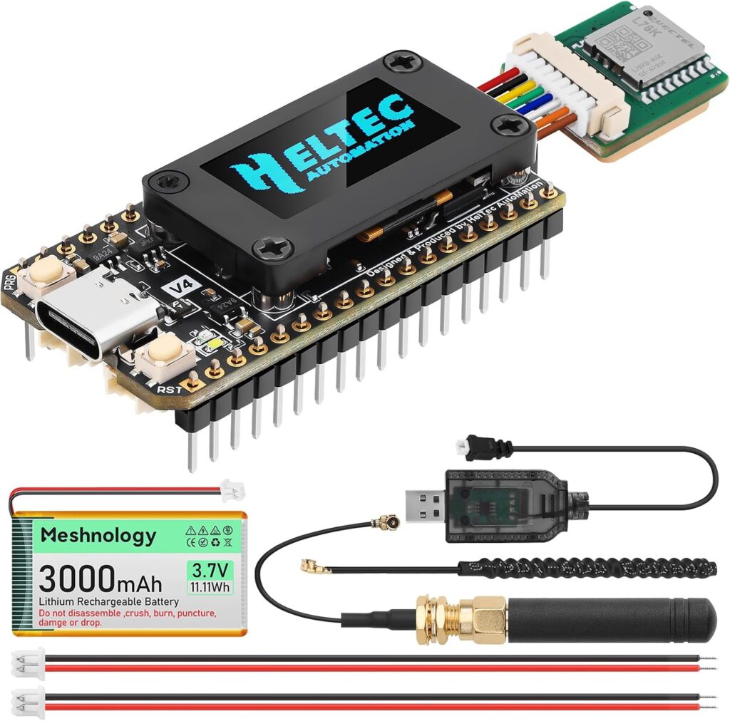
ESP32 LoRa V4 Development Board + L76 GNSS Module + 3000mAh Battery, Upgraded ESP32-S3 SX1262 LoRa WiFi Bluetooth 2MB PSRAM 16MB Flash 915MHz Antenna OLED Support GPS Solar Meshtastic IoTe
Meshnology Upgraded Heltec WiFi LoRa 32 V4 Development Board Kit, Meshtastic Compatible ESP32-S3 SX1262 Off-Grid Texting Radio, Built-in Bluetooth & OLED Display, Project Aziz Network Ready (915MHz)
Leave a Reply