Table of Contents
Building a Custom 4-Button OBS Stream Deck with ESP32 and Arduino
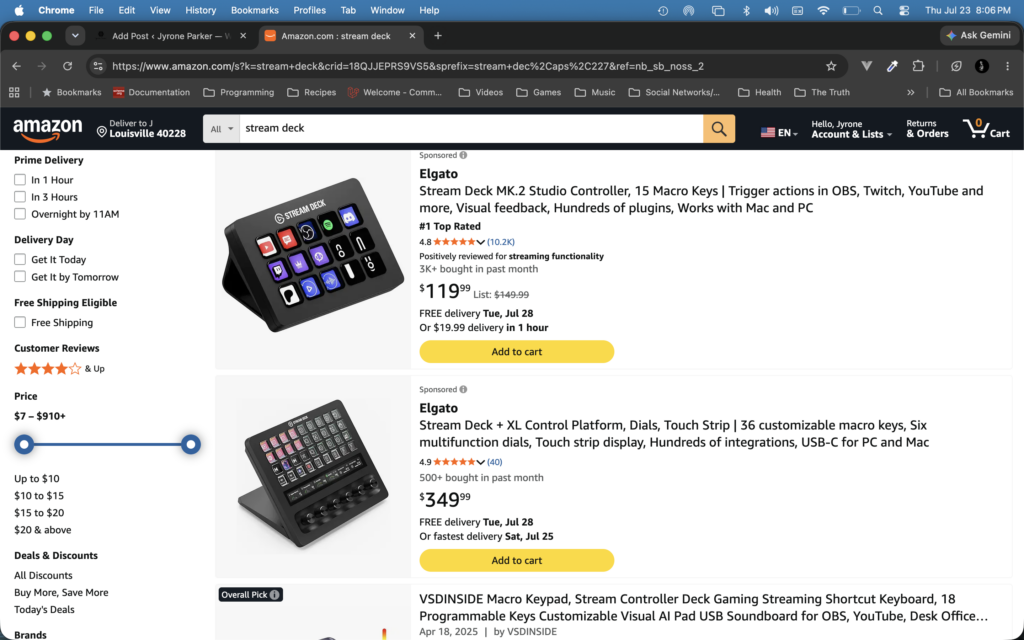
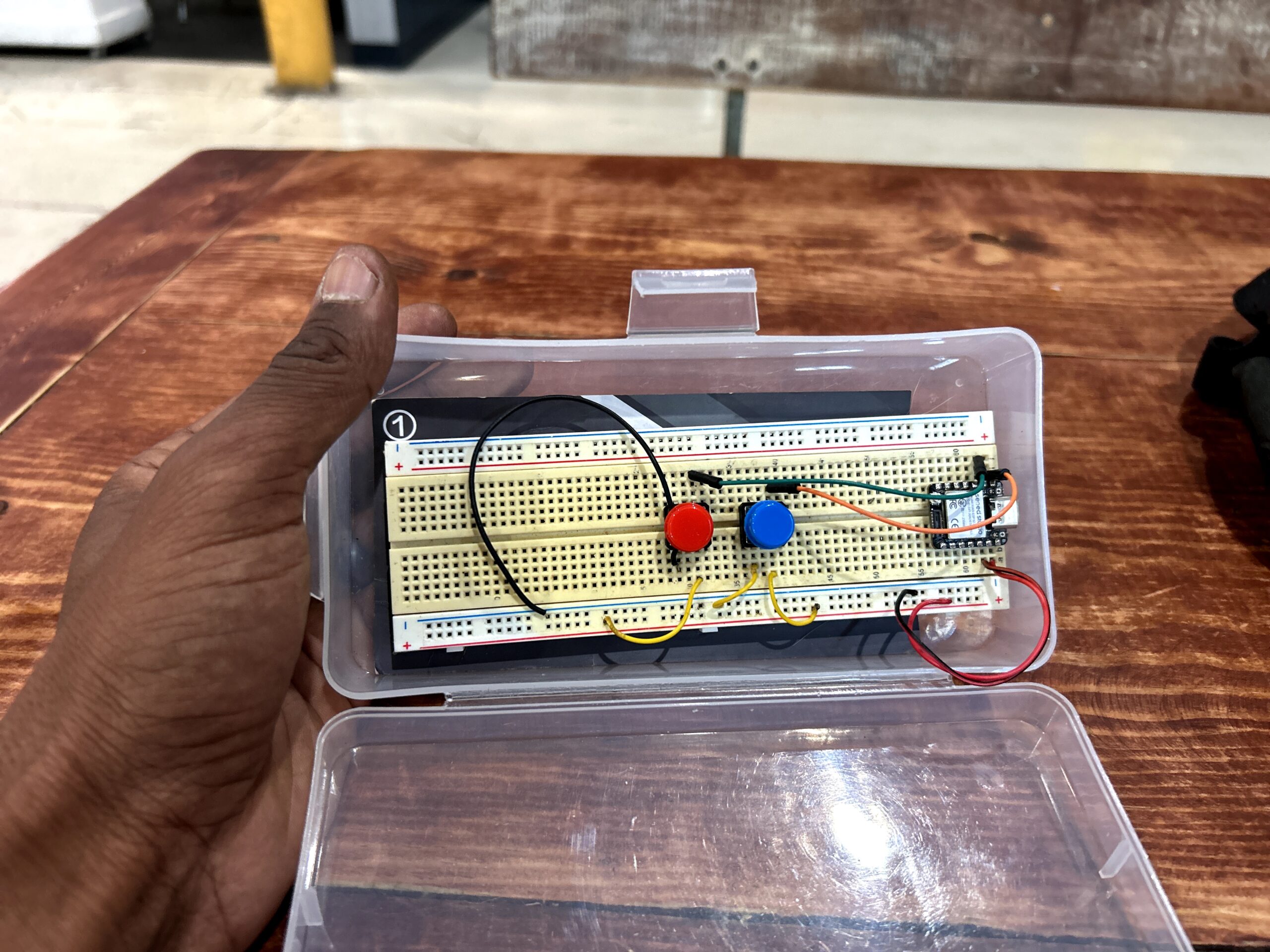
No seriously look at this 💩 Elgato wants $120-$350 for a box with buttons GTFO here! Alas I found myself needing a simple stream box to control my scenes in OBS when I make my tutorials for you lovely people! I have a couple Seeed Xiao S3 Senses so I took one to make my own stream deck. It basically emulates a keyboard to send macro commands nothing too fancy….yet. The original design features 4 buttons although in practice so far I only use two 🤓. The code itself is less than 100 lines and as always is free open-sourced on my Github profile.
Technical Overview
With all my microcontroller projects I use Platform.io to create my projects. This is no different we just have the main.cpp below and I will explain everything in detail.
The architecture turns the board into a native USB Human Interface Device (HID) keyboard. Instead of sending serial communications that require extra software or background scripts running on your PC, pressing a physical button instantly fires off a global keyboard shortcut (Cmd / Windows Key + F7–F10). OBS intercepts these keystrokes like a standard secondary keyboard.
Here is a quick look at the functional breakdown:
| Function | Hardware Pin | Primary Key Combo | Behavior Type |
| Record | GPIO 1 | GUI + F10 | Toggle (Start/Stop) |
| Stream | GPIO 2 | GUI + F9 | Toggle (Start/Stop) |
| Scene 1 | GPIO 3 | GUI + F8 | One-shot Action |
| Scene 2 | GPIO 4 | GUI + F7 | One-shot Action |
Deep Dive into the Code
1. Libraries and Hardware Definitions
At the top of the sketch, we include the necessary USB HID headers and set up our global mapping arrays:
#include <Arduino.h>
#include <USB.h>
#include <USBHIDKeyboard.h>

USBHIDKeyboard Keyboard;

const uint8_t BUTTON_PINS[] = {1, 2, 3, 4}; // GPIO1-GPIO4
const uint8_t NUM_BUTTONS = sizeof(BUTTON_PINS) / sizeof(BUTTON_PINS[0]);
const unsigned long DEBOUNCE_MS = 30;

const uint8_t BUTTON_KEYS[] = {KEY_F10, KEY_F9, KEY_F8, KEY_F7};
const char *BUTTON_LABELS[] = {"Record", "Stream", "Scene 1", "Scene 2"};
const bool BUTTON_IS_TOGGLE[] = {true, true, false, false};
Key Elements:
USBHIDKeyboard Keyboard: Instantiates native USB keyboard capabilities.BUTTON_PINS: Array mapping physical GPIO pins to our four switches.BUTTON_IS_TOGGLE: Differentiates between continuous actions (recording/streaming) and instantaneous commands (changing scenes).
2. Initialization and Internal Pull-ups (setup)
The setup() function handles serial debug initialization, configures the pin modes, and initializes the USB engine:
void setup() {
  Serial.begin(115200);
  unsigned long serialWaitStart = millis();
  while (!Serial && (millis() - serialWaitStart) < 3000) {
    delay(10);
  }

  Serial.println("Stream Deck booting...");

  for (uint8_t i = 0; i < NUM_BUTTONS; i++) {
    pinMode(BUTTON_PINS[i], INPUT_PULLUP);
    lastReading[i] = digitalRead(BUTTON_PINS[i]);
    debouncedState[i] = lastReading[i];
    lastChangeTime[i] = 0;
    toggleOn[i] = false;
  }

  Keyboard.begin();
  USB.begin();
  Serial.println("USB HID keyboard ready");
}
Why INPUT_PULLUP?
Using INPUT_PULLUP enables internal resistors on the microcontroller. This eliminates the need for external resistors on your breadboard or PCB:
- Idle State: Pin reads
HIGH($3.3\text{V}$). - Pressed State: Button connects the pin to
GND, readingLOW($0\text{V}$).
3. Non-Blocking Debounce Logic (loop)
Mechanical switches bounce rapidly when pressed, causing false triggers. To solve this without freezing the controller execution loop, the code implements non-blocking timing logic with a 30ms threshold:
void loop() {
  unsigned long now = millis();

  for (uint8_t i = 0; i < NUM_BUTTONS; i++) {
    bool reading = digitalRead(BUTTON_PINS[i]);

    if (reading != lastReading[i]) {
      lastChangeTime[i] = now;
    }

    if ((now - lastChangeTime[i]) > DEBOUNCE_MS && reading != debouncedState[i]) {
      debouncedState[i] = reading;

      if (debouncedState[i] == LOW) {
        // Trigger action on button press
      }
    }
    lastReading[i] = reading;
  }
}
Using millis() instead of delay() allows the loop to iterate smoothly without blocking performance or dropping inputs across multiple pins.
4. Sending Shortcuts & State Tracking
When a valid press (LOW state) is validated, the controller sends the designated modifier keys, holds them briefly, and releases them:
if (debouncedState[i] == LOW) {
  Keyboard.press(KEY_LEFT_GUI);
  Keyboard.press(BUTTON_KEYS[i]);
  delay(10);
  Keyboard.releaseAll();

  if (BUTTON_IS_TOGGLE[i]) {
    toggleOn[i] = !toggleOn[i];
    Serial.printf("Sent key for '%s' (%s)\n", BUTTON_LABELS[i],
                  toggleOn[i] ? "started" : "stopped");
  } else {
    Serial.printf("Sent key for '%s'\n", BUTTON_LABELS[i]);
  }
}
Modifiers & Key Press Execution:
KEY_LEFT_GUI: Maps to the Windows Key on PC or Command Key ($\text{Cmd}$) on macOS.delay(10): Ensures the host operating system registers the full key sequence before releasing.- Local State Tracking: Tracks whether recording or streaming is active locally via
toggleOn[i].
Note on State Drift: Because this basic implementation operates strictly via unidirectional USB HID key events (sending keys to the host without receiving OBS API status callbacks), state tracking is maintained locally. Interacting directly with the OBS UI via mouse or standard hotkeys can cause the firmware’s internal
toggleOnflag to drift out of sync.
Configuring OBS Studio
To connect the physical hardware macro pad to your OBS actions:
- Connect your microcontroller via USB.
- Open OBS Studio and navigate to Settings > Hotkeys.
- Locate the Start Recording and Stop Recording fields.
- Click the assignment box and press your physical Record Button (GPIO 1). Both start and stop slots will bind to
Cmd + F10(orSuper + F10). - Repeat the process for Stream (
Cmd + F9), Scene 1 (Cmd + F8), and Scene 2 (Cmd + F7).
Summary
This minimal USB HID approach provides a low-latency, reliable control panel for live streaming and recording workflows. Using native USB stacks on boards like the ESP32-S2/S3 or Raspberry Pi Pico lets you build a modular macro pad tailored directly to your production setup. I am going to add on to this design for example I will add some potentiometers to control things like volume and will add a capacitive touch bar. If you want to support this blog and get a microcontroller to boot check my Amazon link below to purchase a Xiao Sense
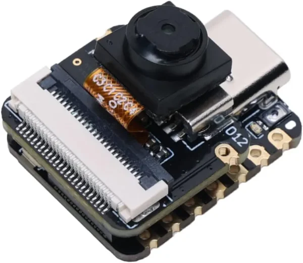
Xiao Sense S3
This is the original base board I used for the Project Aziz facial recognition camera. Capatible with all current and future versions of Project Aziz and a solid board for my microcontroller tutorials.
Leave a Reply